[ANALYSIS] Why is the model showing reactions at all the nodes, though support has not been provided?
Creation date: 6/22/2016 6:58 PM
Updated: 9/5/2017 9:44 AM
There could be two possible reasons for reactions being shown at
unsupported nodes.
1. Structure Type
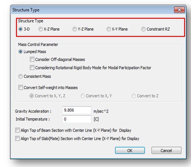
In ‘Structure type’ option, X-Z Plane or Y-Z Plane or X-Y plane option is selected and loads are applied in the third plane. For example X-Y plane is selected and loads are applied along Z plane then all the nodes will be experiencing reactions in Z direction as the structure is restrained in ‘Z’ direction. So for a multi dimensional load application ‘3-D’ Structure type must be selected.
From Main Menu select Structure > Structure Type

2. No Boundary Change assignment for Settlement Load Cases
Settlement Loads have been defined in the model, but boundary change assignment is not done for the same. So for all the static-load cases in post-construction, settlement will be considered first and then static analysis will be carried out.
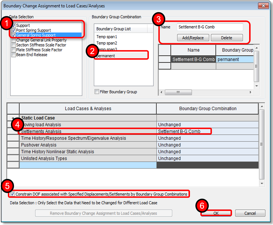
Definition of boundary change assignment can be done as shown below.
Go to Analysis > ‘Boundary Change Assignment’

1. Select all support related data
2. Select all permanent support boundary groups.
3. Give a name for boundary group combination and click on Add/Replace.
4. Select defined boundary group combination for Settlement Analysis
5. Check the option of constraining DOF associated with settlement.
6. Click OK to complete boundary change assignment
unsupported nodes.
1. Structure Type
In ‘Structure type’ option, X-Z Plane or Y-Z Plane or X-Y plane option is selected and loads are applied in the third plane. For example X-Y plane is selected and loads are applied along Z plane then all the nodes will be experiencing reactions in Z direction as the structure is restrained in ‘Z’ direction. So for a multi dimensional load application ‘3-D’ Structure type must be selected.
From Main Menu select Structure > Structure Type
2. No Boundary Change assignment for Settlement Load Cases
Settlement Loads have been defined in the model, but boundary change assignment is not done for the same. So for all the static-load cases in post-construction, settlement will be considered first and then static analysis will be carried out.
Definition of boundary change assignment can be done as shown below.
Go to Analysis > ‘Boundary Change Assignment’
1. Select all support related data
2. Select all permanent support boundary groups.
3. Give a name for boundary group combination and click on Add/Replace.
4. Select defined boundary group combination for Settlement Analysis
5. Check the option of constraining DOF associated with settlement.
6. Click OK to complete boundary change assignment


